
CNC MACHINE QUALITY CONTROL AND PRODUCTION PROCESS
See how TechPro controls machine-bed manufacturing, painting, precision calibration and final CNC machine accuracy throughout production.
CNC Machine Quality Control From Bed to Final Calibration
At TechPro, we build CNC machine quality into one connected process from order confirmation to shipment. Our engineers start with your material, part size, drawing, tolerance and target output to confirm the machine structure, working area, spindle or laser source, motion system, controller, tooling and utilities. We then inspect incoming materials and components, weld and stress-relieve the machine bed, precision-machine the guide-rail, ball-screw, gantry and assembly datums, complete surface preparation, mechanical and electrical assembly, alignment and controller setup, and verify levelness, squareness, spindle geometry, positioning accuracy and repeatability before functional testing, sample processing, final inspection, protective packing and delivery. Review our Honor and Certificates and explore completed CNC Projects to see how these quality checkpoints support real machine applications. Browse our complete CNC machine list to compare available machine types for your production needs.
How TechPro Turns CNC Quality Concerns Into a Complete Control Loop
Experienced CNC buyers repeatedly ask about machine rigidity, precision-machined guide-rail and ball-screw mounting surfaces, spindle runout, axis backlash, repeatability and real-material cutting results. At TechPro, we connect these concerns to one manufacturing workflow: design confirmation, incoming inspection, welding and stress relief, precision machining, mechanical and electrical assembly, geometric calibration, sample testing, protective packing and delivery.
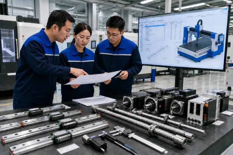
01 — Design Confirmation & Incoming Inspection
We begin with your material, drawing, tolerance, process and output target. Our engineers confirm the machine configuration and approved bill of materials, then inspect the main guide rails, ball screws, servo systems, spindle or laser source, controller and electrical components before they enter production.
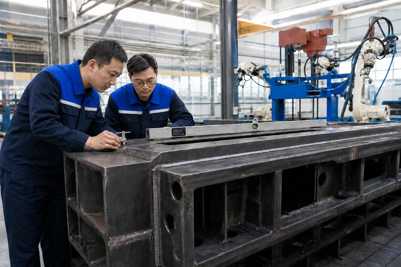
02 — Welding, Rigidity & Stress Relief for Beds
We fabricate the CNC machine bed and gantry to the approved structure, control the joint design and welding sequence, and inspect the key geometry. The required stress-relief treatment stabilizes the frame before machining so rigidity, vibration resistance and long-term alignment begin with a sound foundation.
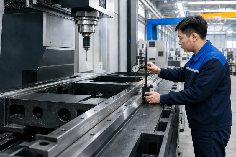
03 — Precision Machining of Datum Surfaces
After stress relief, we precision-machine the guide-rail, ball-screw, gantry, worktable and spindle or cutting-head mounting surfaces. Controlling flatness, straightness, parallelism and squareness at these functional surfaces creates the datum needed for accurate assembly and repeatable motion.
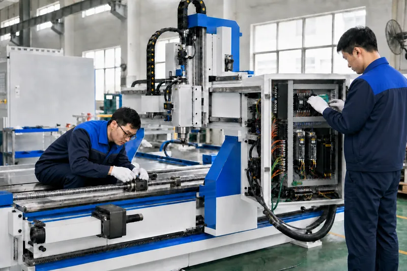
04 — Mechanical Assembly & Electrical Integration
Our technicians install the guide rails, ball screws or rack drives, gantry, spindle or cutting head, servo system, controller, sensors, cable chains, lubrication, cooling and extraction equipment. Clean wiring, secure connections and disciplined component alignment prepare the machine for controlled commissioning.
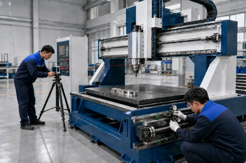
05 — Geometric Calibration & Accuracy Verification
We measure levelness, straightness, parallelism, squareness, spindle runout and verticality, axis backlash, positioning accuracy and repeatability. Mechanical alignment is completed before controller compensation, and the results are checked across the working area with the appropriate precision instruments.
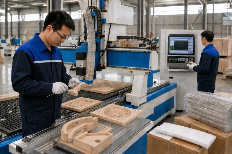
06 — Real-Material Testing, Packing & Delivery
We run functional checks and process a real sample around the confirmed material, drawing, tooling and workholding. Our team reviews dimensions, surface finish, cutting stability and cycle performance, completes the acceptance record, prepares manuals and accessories, and protects the CNC machine for secure shipment and delivery.
How TechPro Builds a Stable CNC Machine Bed
At TechPro, we build CNC machine-bed stability through material and structural review, controlled welding, heat treatment and stress relief, precision machining, and dimensional inspection. Our production team controls the frame load path and verifies the machined datums, guide-rail and ball-screw mounting surfaces, gantry interfaces, and overall geometry before painting and assembly. This rigid, accurate foundation helps the finished CNC machine resist vibration, maintain alignment, and deliver repeatable positioning, consistent surface finish, and reliable long-term production.
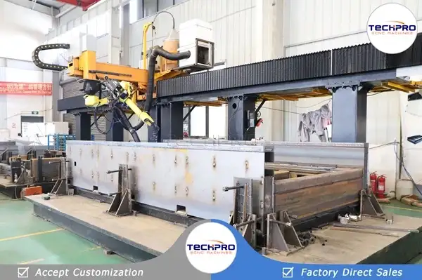
01 — Weld Design and Robotic Fabrication
We begin with high-strength structural or alloy steel, or the approved casting material, selected for the machine size, working area, payload and cutting process. Before fabrication, we inspect material grade, wall thickness, critical dimensions, welding suitability and structural condition against the approved machine specification. Our engineers then define the joint preparation, fixture points and welding sequence so heat input is distributed through the frame instead of concentrating distortion at the guide-rail, ball-screw or gantry mounting zones.
For suitable structures, our robotic welding process improves bead consistency, joint repeatability, safety and production efficiency. Manual inspection remains part of the release process at key joints. This combination creates a rigid load path and a repeatable foundation for the later stress-relief and precision-machining stages.
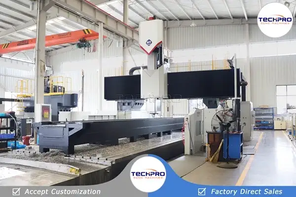
02 — Stress Relief and Precision Bed Milling
Welding and casting create residual stresses that can move a frame after rough machining. We stabilize the structure before final datum machining. For applicable beds, our normal stress-relief annealing range is 500–550°C with a 2–8 hour holding period, followed by controlled furnace cooling for grey iron or air cooling for ductile iron. The selected cycle follows the approved material and structure.
After stabilization, we use precision machining centers to mill the guide-rail seats, ball-screw mounting faces, worktable references and assembly datums. Flatness, straightness and parallelism are controlled on the surfaces that actually carry the motion system. This sequence prevents a superficially accurate frame from changing after assembly and protects long-term rail alignment, backlash control and repeatable axis travel.
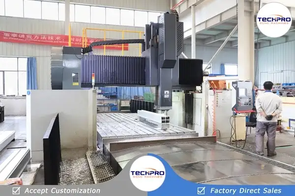
03 — Gantry Milling and Datum Alignment
We machine the gantry rail seats, mating faces and spindle or cutting-head interfaces to one approved datum relationship. Large machining centers allow the critical surfaces to be processed without repeatedly resetting the part, helping us control squareness, parallelism and relative height across the useful working area. We also inspect the gantry structure for local distortion and verify that its mounting faces match the released machine bed.
This is important because a straight rail installed on an inaccurate mounting face cannot produce accurate motion. By creating the geometry in the bed and gantry before assembly, we give the guide rails, ball screws or rack drives a stable reference. The result is smoother travel, lower binding load and more consistent positioning from one side of the machine to the other.
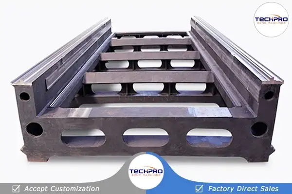
04 — Material and Structural Inspection
For ductile-iron structures, we select heat treatment according to the required strength, toughness and machinability. Multi-temperature or isothermal quenching can increase strength while retaining useful plasticity and toughness. When white-iron structure appears in a surface layer or thin section, high-temperature graphitization annealing or normalizing is used to improve machinability and reduce brittle surface behavior. Our referenced graphitization cycle heats the casting within 550–950°C for 2–5 hours, then uses controlled cooling to 500–550°C before air cooling.
These processes are not isolated specifications. We connect material condition to the next machining step so the casting can be cut consistently and the finished datum surfaces remain stable. The selected cycle is recorded against the machine-bed design and material batch before release.
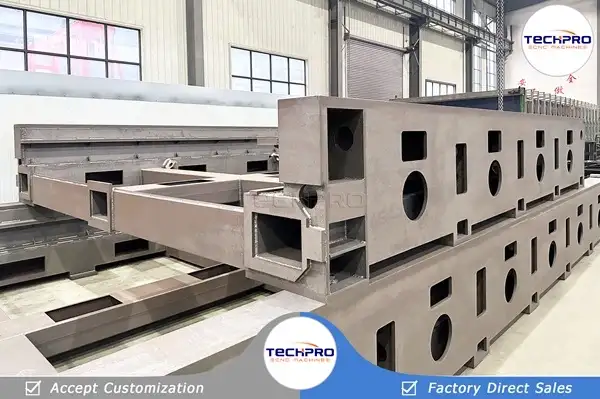
05 — Bed Geometry and Mounting-Surface Inspection
Normalizing refines the pearlite matrix, grain structure and overall uniformity of ductile iron. Our high-temperature normalizing range does not normally exceed 950–980°C, while low-temperature normalizing is generally controlled within 820–860°C. Large castings are handled by a coordinated four-person team after normalizing so movement and post-treatment stress control remain safe and consistent.
Where higher wear resistance or strength is required, we use quenching and tempering: the casting is heated about 30–50°C above Afc1, oil quenched after heat preservation, and then tempered to reduce quenching stress. For selected surfaces, chemical heat treatments such as gas soft chlorination, chlorination, boronizing or sulfurizing can be specified to improve wear, oxidation or corrosion resistance. Every treatment is matched to the approved part function.
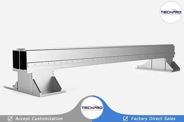
06 — Gantry Manufacturing and Final Release
After heat treatment and precision machining, we inspect the complete bed and gantry as one mechanical foundation. Our checks cover frame geometry, machined datum surfaces, guide-rail and drive mounting positions, gantry interfaces and assembly references. Sandblasting or polishing removes scale and surface defects and creates the controlled surface profile needed for coating adhesion, while precision-machined areas remain protected.
This final release gate prevents welding distortion, rough reference surfaces or an incorrect gantry relationship from being carried into painting and motion-system assembly. It also creates a traceable handoff between fabrication, machining, coating and assembly. When the bed passes this stage, our technicians can install the rails, ball screws, rack drives and cutting system on verified references instead of trying to correct structural errors later.

How TechPro Prepares and Paints the CNC Machine Bed
At TechPro, CNC machine-bed painting is a controlled surface-protection process, not a cosmetic step. After welding, stress relief and precision machining, we remove scale, oil, dust and surface defects, protect guide-rail seats, ball-screw mounts, machined datums and electrical interfaces, then complete filling, sanding, water grinding, priming, drying and topcoat application in sequence. Each layer is inspected before the next is applied, helping the finished frame maintain coating adhesion, corrosion resistance, a consistent factory finish and the mechanical accuracy established during earlier manufacturing stages.
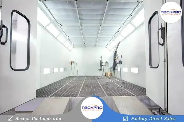
01 — Paint Booth Preparation and Surface Cleaning
Before painting, we inspect the casting or welded frame and trim uneven surface areas without changing the precision-machined datums. The bed is then rinsed or brushed with metal cleaner or clean industrial gasoline to remove oil, dirt, grinding residue and other contamination. The spray area and equipment are prepared at the same time so dust or moisture is not introduced after cleaning.
We mask guide-rail seats, ball-screw mounting faces, threaded holes, electrical interfaces and assembly references before coating. This preparation improves coating adhesion and prevents paint thickness from affecting later alignment or fastener seating. A clean, protected substrate is the starting point for the complete primer and topcoat system and directly influences corrosion resistance, surface uniformity and the durability of the finished machine appearance.
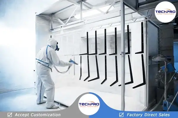
02 — Filling, Sanding and Primer Application
Surface depressions are filled only after cleaning. We mix the approved putty with the specified curing agent and apply it in controlled layers. Where vinyl perchloride or perchloroethylene filler is used, each scraping is kept to approximately 0.5 mm and allowed to dry before the next layer. Thick, uncured filler can shrink, trap contamination or create an uneven coating, so drying and surface correction are checked between applications.
After the filled area cures, our technicians sand it level and completely remove grinding slurry and dust. Primer is fully stirred, adjusted to the required application viscosity and applied evenly by the selected brushing, spraying or dipping method. The surface is inspected before it proceeds, giving later coats a smooth, clean and consistently bonded foundation.
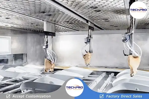
03 — Robotic Spray Coating for Consistent Coverage
On suitable frames and batches, robotic or controlled spray application helps us keep spray distance, overlap, travel speed and layer sequence consistent over large surfaces and complex frame sections. This improves repeatability between machines while reducing dry spray, uneven color, excessive film build, sagging and bubbles. Corners, ribs, welded joints and recessed areas receive deliberate coverage rather than relying only on broad external surfaces.
Our technicians still inspect the coating during application and correct local areas before the film cures. Precision datums and protected interfaces remain masked throughout the spray stage. The goal is not simply a glossy surface; it is an even coating system that isolates the steel or casting from moisture and factory contamination while preserving every mechanical reference needed for accurate assembly.
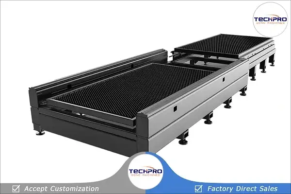
04 — Bed Preparation and Water Grinding
After the filler dries, we use controlled sanding or water-grinding methods to level the prepared bed. Anti-rust water is used during wet grinding to protect exposed cast or steel surfaces. After every pass, our team removes grinding slurry, dust and loose material before inspecting the surface again. If grinding exposes metal, the area is cleaned and the matching primer is restored before the next coating step.
Following the final putty polish and cleaning, a second vinyl-chloride primer can be applied where specified to improve paint-film flatness and gloss. This repeated clean–inspect–prime sequence prevents abrasive residue or moisture from being sealed below the coating and creates a more uniform surface for the topcoat, especially around casting depressions, welded transitions and other visually critical areas.
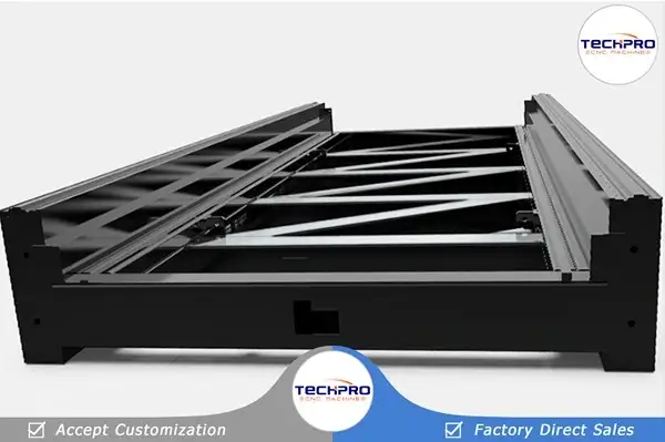
05 — Primer and Topcoat Layer Control
We normally apply 2–3 primer coats as required for even coverage, rust protection and adhesion. Each coat is allowed to dry completely—typically about 1–2 hours depending on the primer and ambient temperature—before the surface is checked, corrected and cleaned with compressed air and a non-woven cloth. This prevents dust, sanding residue and weak intercoat bonding from being hidden below the topcoat.
The topcoat is then sprayed in 2–3 controlled coats. We normally allow approximately 30–60 minutes between layers, adjusted for the coating system and shop conditions. Spray overlap, leveling, color and gloss are monitored, and the frame cures in a ventilated environment protected from dust and moisture. Where the coating specification requires it, controlled heating can accelerate curing and improve film hardness and wear resistance.
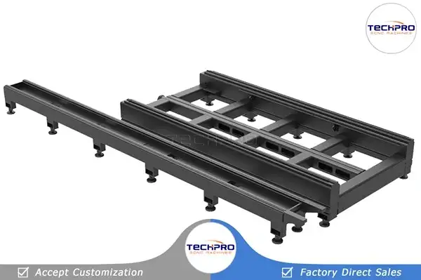
06 — Finished Frame Inspection and Release
After the final coat cures, we inspect the machine bed for complete coverage, coating adhesion, bubbles, sagging, dust inclusions, impurities, exposed metal, uneven color and local defects. Areas that do not meet our finish standard are repaired and reinspected before the frame is released. We also remove masking carefully and confirm that machined datums, threaded connections and assembly interfaces remain clean.
Spray guns and related equipment are cleaned with detergent or the specified cleaning fluid so the next production batch begins with controlled equipment condition. The accepted frame is then cleaned and transferred to mechanical and electrical assembly. This closing checkpoint protects the corrosion barrier, professional appearance and verified interfaces that support accurate guide-rail, ball-screw and gantry installation.

How TechPro Calibrates CNC Machine Accuracy
At TechPro, CNC machine accuracy is established through mechanical alignment, electrical commissioning and measured verification. Our technicians level the machine; align the guide rails, ball screws or rack drives, gantry and spindle or cutting head; and check straightness, parallelism, squareness, spindle runout, verticality, backlash, positioning accuracy and repeatability with CMM, laser measurement, precision levels, indicators, micrometers and calipers. We then verify repeated axis movement and process a sample with the confirmed material, tooling and workholding, connecting calibration data directly to the customer’s production result.
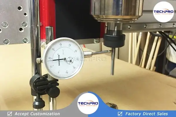
01 — Spindle Runout and Tool-Center Inspection
We inspect the spindle or cutting head at the functional tool center instead of relying only on the motor specification. Precision indicators and electric-shaft measuring instruments are used to check rotational condition, spindle runout and operating consistency. Where applicable, we also check the taper, collet or toolholder relationship, because error at the tool center directly affects cutting load distribution.
Excessive runout can make one flute carry more load than another, reduce tool life, widen the cut and leave an uneven surface. We therefore connect spindle measurement to verticality and actual sample cutting. This verifies that the installed spindle, gantry and machine bed work as one rigid system and that the tool follows the intended axis under real operating conditions.
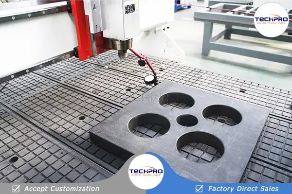
02 — Probe Measurement and Datum Verification
Coordinate measurement is used to verify the three-dimensional relationship between the spindle, worktable, gantry and approved machine datums. A CMM can measure programmed points, lines and surfaces on a reference part, helping us evaluate dimensional and geometric features with a repeatable measuring routine. Probe measurements on the machine complement this by checking the working relationship where the part will actually be processed.
Our technicians compare multiple points instead of judging accuracy from one location. This reveals twist, squareness error or local deviation across the working area and reduces variation from manual single-point inspection. The result is a clearer link between the released mechanical datums, assembly alignment and the dimensions that the customer expects from the finished CNC process.
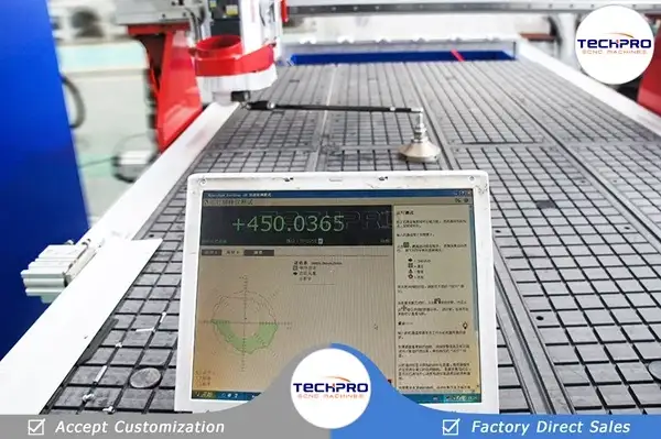
03 — Axis Positioning With Laser Measurement
We use laser interferometer measurement where required to evaluate actual linear displacement and positioning behavior along the commanded axis. The laser data helps identify scale error, pitch-related movement, compensation requirements and the difference between the controller position and the machine’s measured position. Repeated measurements are used to assess positioning accuracy and repeatability rather than relying on a single traverse.
After mechanical correction, the measured results guide controller compensation and verification across the usable travel. We also use precision indicators to check spindle verticality and angular relationships. This sequence follows the practical intent of machine-tool positioning tests: measure the axis directly, correct the mechanical cause first, then confirm that commanded movement, return movement and repeated positioning produce a stable result.
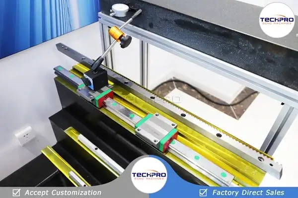
04 — Guide-Rail Levelness and Straightness
Before fine calibration, we level the machine and inspect guide-rail straightness, parallelism and installation condition. Precision levels measure foundation and bed levelness, while indicators and reference surfaces show how the rail geometry changes along its full length. We correct mounting contact and alignment before tightening the system to the approved sequence.
A precision rail cannot deliver accurate motion if its machined seat is twisted or contaminated. Incorrect rail geometry creates binding, uneven bearing load, vibration and position error that changes from one end of the machine to the other. By checking the complete travel, we protect smooth axis movement and give the ball screw, rack drive, gantry and spindle a consistent reference for later backlash, squareness and repeatability tests.
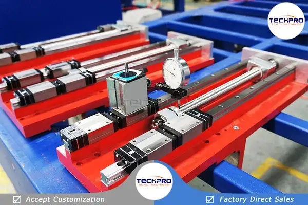
05 — Ball-Screw Backlash and Repeatability
We inspect the installed ball screw or rack drive, bearing supports, coupling condition and axis preload as a complete drive system. Using indicators and repeated reverse moves, our technicians check lost motion when the axis changes direction. We also command the axis to the same position repeatedly and approach from different directions to evaluate practical repeatability and the stability of the installed components.
Backlash is not only a software value. It can come from installation, bearing adjustment, coupling movement, drive engagement or structural flex. We correct the mechanical source before applying controller compensation. This protects circle quality, pocket dimensions, hole position and surface finish, especially when the tool path changes direction under load. The final result is verified over the working area, not only near the machine home position.
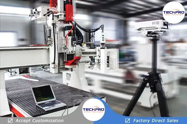
06 — X/Y/Z Geometric Accuracy and Final Test
We complete the calibration loop by checking X/Y/Z travel, axis squareness, spindle or cutting-head geometry, positioning accuracy and repeatability across the usable work area. Micrometers and calipers support daily dimensional checks, while precision indicators, laser measurement and coordinate inspection are used for the checkpoints that require finer geometric data. Electrical commissioning confirms servo response, controller parameters, sensors and safety functions before production testing.
Finally, we process a real sample using the confirmed customer material, drawing, tooling and workholding whenever the project requires it. Our team reviews dimensions, hole position, edge or surface finish, cutting stability and cycle behavior. This real-material test connects calibration data to the customer’s production result and completes our quality-control chain before acceptance records, manuals, accessories, protective packing and delivery.

Our CNC Machine Manufacturing and Quality Control Process
Application Review & Engineering
We review your material, workpiece size, drawing, tolerance, process and output target, then confirm the machine structure, working area, spindle or laser source, motion system, controller, tooling and utility requirements.
Materials, Components & Machine Bed
We prepare the steel or cast structure and inspect the main mechanical, electrical and motion components against the approved configuration before they enter production.
Welding, Stress Relief & Precision Machining
We control the welding sequence, key joints and frame geometry, apply the required stress-relief treatment, then precision-machine the guide-rail, ball-screw, gantry and assembly mounting surfaces.
Surface Finishing, Assembly & Electrical Integration
We clean, prime, sand and paint the frame, then install the gantry, worktable, guide rails, ball screws, spindle or cutting head, drives, controller, sensors, lubrication, cooling and extraction systems.
Alignment, Calibration & Functional Testing
Our technicians align the complete motion system and check levelness, straightness, squareness, spindle verticality, backlash, positioning accuracy, repeatability, axis travel, safety functions and controller parameters.
Sample Processing, Final Inspection & Delivery
We run functional tests and sample processing with the confirmed tooling and program, inspect key dimensions and surface results, complete the acceptance record, protect the machine for transport and prepare manuals, accessories and delivery documentation.
CNC Machine Quality Control FAQ
Frequently Asked Questions
How Do We Verify That a CNC Machine Is Rigid Enough for the Customer’s Material?
We match the machine-bed and gantry structure to the customer’s material, part size, tooling, accuracy and output target before production. During fabrication, we control joint preparation, welding sequence and frame geometry, then apply the required heat treatment or stress relief before precision-machining the guide-rail, ball-screw, gantry and worktable datums. We inspect the completed foundation and connect those checks to real cutting performance, because rigidity affects vibration, tool load, edge quality and repeatable accuracy. Send us your material, maximum thickness, part drawing and expected cycle, and our engineers will confirm the appropriate structure and acceptance plan.
How Do We Control Backlash and Repeatability in the Ball-Screw or Rack-Drive System?
We inspect the complete drive system—not only the controller value. Our technicians check ball screws or rack drives, bearing supports, couplings, preload, guide-rail alignment and structural movement, then use indicators and repeated reverse-direction moves to detect lost motion. We correct mechanical causes before applying controller compensation and repeat the positioning test from both directions across the usable travel. This protects circular interpolation, pocket dimensions, hole position and surface finish when the axis changes direction. For your project, we can include the required positioning and repeatability checks in the machine acceptance plan.
How Do We Check Spindle Runout, Verticality and Tool-Center Accuracy?
We measure the installed spindle or cutting head at the functional tool center with precision indicators and electric-shaft measuring instruments, and we check its relationship to the gantry, worktable and machine datum. Where applicable, we also inspect the taper, collet or toolholder interface. We then verify spindle verticality, rotational condition and sample-cut results, because excessive runout can increase tool load, shorten tool life, widen a cut and leave an uneven surface. Our final decision combines measurement data with the finish and dimensions produced under the confirmed tooling and process conditions.
Do We Measure CNC Accuracy Across the Full Working Area or Only Near Machine Home?
We verify the motion system across the usable X/Y/Z travel, not at a single convenient point. Our technicians level the machine and check guide-rail straightness and parallelism, axis squareness, gantry geometry, spindle verticality, positioning accuracy and repeatability at multiple locations. Depending on the machine and checkpoint, we use precision levels, indicators, CMM or probe measurement, laser measurement, micrometers and calipers. Mechanical alignment is completed before controller compensation, and repeated moves confirm that the result remains stable throughout the working area. Tell us your critical part size and tolerance so we can plan the relevant checkpoints.
Can We Run a Real-Material Cutting Test Before the CNC Machine Is Shipped?
Yes. When the project requires it, we process a sample using the confirmed customer material, drawing, tooling, workholding and program before shipment. Our team reviews dimensions, hole or profile position, edge quality or surface finish, cutting stability, tool behavior and cycle performance. We use the result to connect the machine’s rigidity, spindle condition, backlash, calibration and process settings to the customer’s actual production goal. We can provide sample photos or video and record the agreed acceptance result before manuals, accessories, protective packing and delivery preparation are completed. Send your drawing and material details when requesting the test.
What Quality-Control Records and Project Information Should Be Confirmed Before Shipment?
We first need your material, maximum workpiece size and thickness, drawing or sample, required tolerance, process steps, target output, tooling and workholding preference, electrical supply, air, extraction or cooling requirements, and any controller or automation preference. Our engineers use this information to confirm the machine structure, working area, motion system, spindle or laser source, approved component configuration and test plan. Before shipment, we complete the agreed functional checks, dimensional or sample-test record, machine configuration, manuals, accessories and packing preparation. Sharing these details early lets us build and test the machine around the work you actually need to produce.
Can I Get a CNC Machine Testing Video Before Shipping?
Yes. Before shipment, we can record a machine testing video based on the confirmed configuration and acceptance plan. The video can show machine startup, controller operation, axis movement, spindle or cutting-head operation, safety functions and, when agreed for the project, real-material sample processing. We can also include the test setup, tooling, workholding, key dimensions and finished surface or edge result so you can review how the machine performs for your application. Send us your material, drawing and the checkpoints you want to see before production testing, and our engineers will incorporate them into the pre-shipment review.
How Do We Ensure Safe Packaging for Ocean Shipping?
We prepare each CNC machine for ocean transport after final inspection and the agreed acceptance checks. Our team cleans the machine, secures the moving axes, spindle or cutting head, cables, controller and loose accessories, applies moisture and corrosion protection where required, protects exposed precision surfaces, and fixes the machine to an export packing base with reinforced supports selected for its size and shipping route. Components removed for transport are labeled and packed with the manuals and accessories. Before release, we inspect the packing condition and can provide loading and packing photos or video. Tell us the destination port, unloading conditions and any local crating requirements so our team can confirm the shipment plan.

Explore CNC Machines Built and Tested by TechPro
We apply the same connected quality-control process to the CNC machines we build for different materials and production goals. From machine-bed stability and motion-system alignment to electrical commissioning, accuracy verification and real-material testing, our engineers match each inspection checkpoint to the machine configuration and the customer’s application.
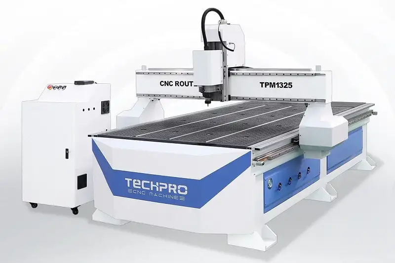
CNC Router Machines
We inspect machine-bed rigidity, guide-rail and ball-screw or rack installation, spindle runout, axis backlash and repeatability, then confirm cutting performance with the agreed material, tooling and workholding.
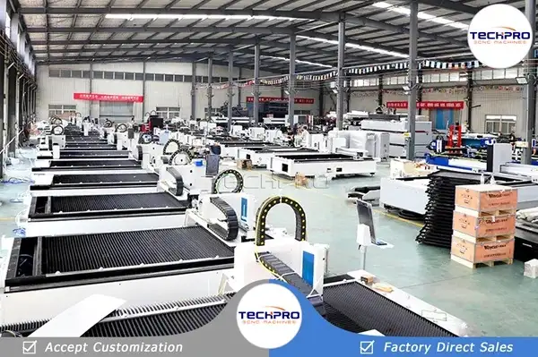
Laser Cutting Machines
We control bed and gantry stability, guide and drive alignment, laser-head movement, electrical and safety functions, full-working-area positioning and cutting quality before the machine is prepared for delivery.
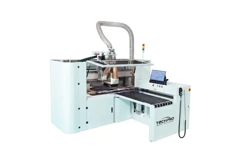
Panel Furniture Machines
We coordinate cutting, drilling, feeding, positioning and electrical systems as one production workflow, then check panel dimensions, hole alignment, repeatability and operating performance with representative materials.
READY TO BUILD A CNC MACHINE AROUND YOUR PRODUCTION GOALS?
Share your material, part size, drawing, tolerance, process and target output. Our engineers will connect your application requirements with the machine structure, motion system, controller, tooling, quality checks and acceptance plan, and can prepare a factory-inspection or real-material sample-cutting video for the agreed pre-shipment review.